#uart driver
Explore tagged Tumblr posts
Visit Tumblr Blog
Explore Tumblr blogs with no restrictions, modern design and the best experience.
Last Seen Tumblr Blogs


Fun Fact
Kazakhstan’s Minister of Communications and Informatics has blocked the Tumblr site because it contained 60 sites of terrorism, extremism, and pornography in 2015.
Text
https://www.futureelectronics.com/p/semiconductors--signal-interface--rs-485-422/sp485ecn-l-maxlinear-4021275
RS-485 Transceiver, RS485 converter, Line Driver, RS 422 converter, rs485 cable
SP485E Series 10 Mbps 5 V Enhanced Low EMI Half Duplex RS-485 Transceiver-NSOIC8
#Signal Interface#RS 485/422#SP485ECN-L/TR#MaxLinear#converter#Line Driver#rs485 cable#Receiver#USB#uart driver#Data rate#supply voltage#rs485 pinout#RS-485#rs485 usb converter#ESD voltage
1 note
·
View note
Text
On Celebrating Errors

Isn't it beautiful? The lovely formatted tables of register and stack contents, the trace of function addresses and parameters, the error message ... it's the most beautiful kernel panic I have ever seen.
Why on earth would I be so excited to see a computer crash? What could possibly be beautiful about a kernel panic?
This kernel panic is well-earned. I fought hard to get it.
This kernel panic came from a current NetBSD kernel, freshly compiled and running on Wrap030, my 68030 homebrew computer. It is the result of hours upon hours of work reading through existing code, scattered documentation and notes, writing and rewriting, and endless compiling.
And it's just the start.
As I've said before, a goal of this project has always been to build something capable of running some kind of Unix-like operating system. Now that I finally have all the necessary pieces of hardware, plus a good bootloader in ROM, it's time to give it a shot. I'm not that great with this type of programming, but I have been getting better. I might just be able to brute force my way through hacking together something functional.
It is hard.
There is some documentation available. The man(9) pages are useful, and NetBSD has a great guide to setting up the build environment for cross-compiling the kernel. There are some published papers on what some people went through to port NetBSD to this system or that. But there's nothing that really explains what all these source code files are, and which parts really need to be modified to run on a different system.
I had a few false starts, but ultimately found an existing 68k architecture, cesfic, which was a bare minimum configuration that could serve well as a foundation for my purposes. I copied the cesfic source directory, changed all instances of the name to wrap030, made sure it still compiled, then set about removing everything that I didn't need. It still compiled, so now it's was time to add in what I did need.
... how ... do I ... ?
This is where things get overwhelming very quickly. There is documentation on the core functions required for a new driver, there's documentation on the autoconf system that attaches drivers to devices in the tree, and there's plenty of drivers already to reference. But where to start?
I started by trying to add the com driver for the 16550 UARTs I'm using. It doesn't compile because I'm missing dependencies. The missing functions are missing because of a breaking change to bus.h at some point; the com driver expects the new format but the cesfic port still uses the old. So I needed to pull in the missing functions from another m68k arch. Which then required more missing functions and headers to be pulled in. Eventually it compiled without error again, but that doesn't mean it will actually run. I still needed to add support for my new programmable timer, customize the startup process, update hardware addresses, make sure it was targeting 68030 instead of 68040 ...
So many parts and pieces that need to be updated. Each one requiring searching for the original function or variable declaration to confirm expected types or implementation, then searching for existing usages to figure out what it needs ... which then requires searching for more functions and variable types.
But I got something that at least appeared to have all the right parts and compiled without error. It was time to throw it on a disk, load it up, and see what happened.
Nothing happened, of course. It crashed immediately.
I have no debugging workflow I can rely on here, and at this stage there isn't even a kernel console yet. All I could do was add little print macros to the locore startup code and see where it failed. Guess, test, and revise.
I spent a week debugging the MMU initialization. If the MMU isn't properly configured, everything comes to an abrupt halt. Ultimately, I replaced the cesfic machine-specific initialization code and pmap bootstrapping code with functions from yet another m68k arch. And spent another day debugging before realizing I had missed a section that had comments suggesting it wasn't for the 68030 CPU, but turned out to be critical for operation of kernel memory allocation.
Until this point, I was able to rely on the low-level exception handling built into my bootloader if my code caused a CPU exception. But with the MMU working, that code was no longer mapped.
So then came another few hours learning how to create a minimal early console driver. An early console is used by the kernel prior to the real console getting initialized. In this case, I'm using the MC6850 on my mainboard for the early console, since that's what my bootloader uses. And finally the kernel was able to speak for itself.
It printed its own panic.
The first thing the kernel does is initialize the console. Which requires that com driver and all the machine-specific code I had to write. The kernel is failing at its step #1.
But at least it can tell me that now. And given all the work necessary to get to this point, that kernel panic data printing to the terminal is absolutely beautiful.
#troubleshooting#coding#os development#netbsd#homebrew computer#homebrew computing#mc68030#motorola 68k#motorola 68030#debugging#wrap030#retro computing
69 notes
·
View notes
Text
We're vibin' with Claude 3.7 and writing uBlox drivers 😎🤖🛰️
Heeeey, we're just having a super chill vibe here at the desk of Ladyada—writing a driver for the uBlox M8Q
https://blog.adafruit.com/2024/09/10/a-mini-gps-from-ublox-with-i2c-and-uart
, which has both I2C and UART interfaces. As expected, it can do everyday NMEA output, but it can also do UBX, a "compressed" protocol for advanced data reads and writes over I2C/UART—or even SPI on some other chips.
However, the UBX protocol is a hugely complex driver to implement, with dozens of commands and hundreds of flags. But why stress when you can viiiibe? We're using this beast of a spec as an excuse to try out the new Claude 3.7, which is doing great at chomping through the UBX documentation roughage and giving us some nice code on the other side. Within an hour, we're able to connect and switch to UBX mode by sending a well-formed message and receiving an ACK.
What we like about coding with a good LLM is that it does the work we sometimes get lazy over, like handling various error conditions, timeouts, and verbose error messages.
13 notes
·
View notes
Text
Embedded Systems Course in Pune with Placement
If you’re in Pune and serious about a career in embedded systems or IoT, there’s a good chance you’ve heard the name Technoscripts. Since 2007, this institute has helped thousands of students and professionals move beyond theory and into real embedded jobs. Whether you’re a fresher aiming to break into the core electronics field or someone looking to switch domains, Technoscripts has built a reputation for being one of the most reliable places to start that journey.
Let’s take a closer look at what makes this place different — and why so many students recommend it.
A Strong Foundation in Embedded Systems Training
Technoscripts didn’t just pop up recently. It’s been around for over 18 years, which means they’ve seen the industry change and evolve — and they’ve updated their training along with it. From basic microcontroller programming to more advanced topics like RTOS, device drivers, and IoT, their curriculum is built to match what companies are actually looking for.
The institute runs its classes in Shivaji Nagar, Pune, and offers both online and offline batches. So whether you’re a college student, a working professional, or someone in between, you can find a batch that fits your schedule.
Learning by Doing — The Practical Approach
One of the biggest reasons students choose Technoscripts is the hands-on learning. Here, you won’t just be sitting through theory lectures. You’ll get your hands dirty — working with sensors, microcontrollers, and various protocols like UART and I2C.
Each course includes at least two live projects, which gives you actual project experience. These aren’t just dummy projects either — they’re built to mimic what engineers work on in the real world. That experience becomes a big plus when you start applying for jobs.
And because the batches are small, you get personal attention. Trainers are not just teaching from slides — they’ve worked in the industry and know how things really work. Students often say the trainers are supportive, clear with concepts, and genuinely interested in helping you learn.
Course Options That Fit Different Goals
Whether you’re just starting out or looking to specialize, Technoscripts has courses for every level.
Embedded Systems Course in Pune with Placement — This is their flagship course. It runs for about 4 months and covers everything from C programming and 8051 microcontrollers to ARM, PIC, and wireless technologies. It’s designed to get you job-ready.
IoT Training — One of the first IoT-focused courses in India, this one teaches you how to build smart, connected devices. It’s ideal if you want to get into future-focused tech.
Automotive Embedded, MATLAB, and AUTOSAR — These are great if you’re targeting specific sectors or want to move into niche roles.
Post Graduate Diploma in Embedded Systems — Perfect for beginners, this course gives you a solid foundation and gradually builds up your skills with lab-based learning.
Solid Placement Support That Actually Works
A lot of institutes say they offer placements. Technoscripts actually delivers. Their placement team is active, always coordinating interviews, helping with resumes, and preparing students with mock interviews and soft skills sessions.
They have ties with several companies, from big MNCs to core embedded startups. That means more chances for students to land roles that actually match their training. You’ll find Technoscripts students placed in companies working on automotive, medical, and industrial applications.
The feedback is consistent — students who put in the effort get placed.
“I got placed in Spark as an Embedded Developer. The training was hands-on and the support from the placement team was excellent,” says one student.
“Technoscripts is the best training institute in Pune. I got placed in a good company and learned so much through practical projects,” says another.
Industry Exposure and Certifications That Matter
Technoscripts doesn’t operate in a vacuum. They keep their training relevant by partnering with companies, organizing guest lectures, and even arranging internships and industry visits.
They also provide NASSCOM®-certified training, which adds weight to your resume and helps during hiring processes.
Their courses are regularly updated to include trending technologies like STM32 microcontrollers, Embedded Linux, and IoT protocols, so you’re not learning outdated stuff.
Flexible Learning Options for All Schedules
Not everyone has the same timetable. That’s why Technoscripts offers:
Regular batches
Fast-track programs
Weekend classes
Early morning & evening options
Live online training with project kits
Even if you’re working full-time, you can still attend and learn at your pace.
A Supportive, Student-First Atmosphere
Beyond the tech and tools, what really makes Technoscripts stand out is its student-friendly environment. The faculty is approachable, and the vibe is encouraging. They even host webinars, meetups, and project expos to keep the energy going.
One student said it best:
“The atmosphere here is very healthy. There are regular live projects, webinars, and opportunities to apply what you learn.”
A Few Areas to Improve — And They’re Listening
Like any place, Technoscripts isn’t perfect. Some students have said they’d like even more extracurricular activities or career-focused workshops. The good part? The institute listens. They’ve been adding more events and soft skills sessions over time to give students a well-rounded experience.
Final Thoughts
Technoscripts Embedded Institute isn’t just about teaching you how to blink an LED. It’s about building a career in embedded systems, step by step — with practical skills, real projects, and strong placement backing.
Whether you’re looking for your first core job, planning to switch domains, or just want to build something real, Technoscripts can be your launchpad.
If you’re serious about embedded systems, this is a great place to start.
0 notes
Text

ATMEGA328P-AU Embedded System for Atemel IC Distributor Atmega328p specification:IC MCU 8BIT 32KB FLASH 32TQFP. Core Processor:AVR Core Size:8-Bit Speed:20MHz Connectivity:I2C, SPI, UART/USART Peripherals:Brown-out Detect/Reset, POR, PWM, WDT Number of I/O:23 Program Memory Size:32KB (16K x 16) Program Memory Type:FLASH EEPROM Size:1K x 8 RAM Size:2K x 8 Voltage - Supply (Vcc/Vdd):1.8V ~ 5.5V Data Converters:A/D 8x10b Oscillator Type:Internal Operating Temperature:-40°C ~ 85°C (TA) Mounting Type:Surface Mount Package:32-TQFP (7x7) Atmega328 Datasheet here. Note:Online picture for date code only for refference,different lot date code meybe differenct than online picture.All date code or lot number is as actual received shipment. Besides,if you didn't find the correct mcu parts number in our site online,you can also chat with us to confirm due to there are much more inventory parts list maybe not list online yet.Know more business about us. About ATMEGA328P-AU Online Price and MOQ: As for MOQ you see in the quantity blanket,MOQ of this atmega328 mcu is 100 units,if you interested with much more quantity than MOQ online,welcome to chat with us via whatsapp to consult the best support. ...... Other more electronic components inventory stock are not able to post online,welcome drop us email or chat via whatsapp to know more. About Payment: We usually accept bank transfer,credit card payment,like Visa,MasterCard.,Western Union etc. About Warranty: All the parts provided are same quality as original,so quality is same as offical 1 year warranty. About Us: Chengsuchuang are relable and trustworth electronics hardware supplier from China,we are in the electronic components fields since 2014 year,and got lots of experience in the electronics hardware supply chain.If you are looking for something else about other pcb project for the electronic components bom list,they are also available to supply.Integrated circuits including power ic, logic ic, control ic, driver ic, monitor ic, inerface ic etc.MCU including consumer electronics project,industrial,automobile and medical fields etc. The electronic components distribution brand including ADI,Micron,Samsung,Atmel, Microchip, ST, TI, NXP, INFINEON,Cypress,Altera,Xilinx,ON,TDK,Toshiba,Panasonic etc.The more interested parts number quotation request,welcome drop us email to send a enquiry. If you are looking for a reliable and trustworth ic supplier,then this is a good place you comes.Contact us to talk via whatsapp with sourcing request for quotation,we'll respond you soon. Know more about company product catagory here. Read the full article
0 notes
Text
Why India’s Drone Industry Needs Periplex: The Hardware Tool Drones Didn’t Know They Needed
As drones fly deeper into critical roles — from agricultural intelligence to autonomous mapping, from disaster response to military ops — the hardware stack that powers them is undergoing a silent revolution.
At the center of that transformation is Periplex — a breakthrough tool from Vicharak’s Vaaman platform that redefines how drone builders can interface with the real world.

What is Periplex?
Periplex is a hardware-generation engine. It converts JSON descriptions like this:{ "uart": [ { "id": 0, "TX": "GPIOT_RXP28", "RX": "GPIOT_RXN28" } ], "i2c": [ { "id": 3, "SCL": "GPIOT_RXP27", "SDA": "GPIOT_RXP24" }, { "id": 4, "SCL": "GPIOL_63", "SDA": "GPIOT_RXN24" } ], "gpio": [], "pwm": [], "ws": [], "spi": [], "onewire": [], "can": [], "i2s": [] }
…into live hardware interfaces, directly embedded into Vaaman’s FPGA fabric. It auto-generates the FPGA logic, maps it to kernel-level drivers, and exposes them to Linux.
Think of it as the “React.js of peripherals” — make a change, and the hardware updates.
Real Drone Applications That Truly Need Periplex
Let’s break this down with actual field-grade drone use cases where traditional microcontrollers choke, and Periplex thrives.
1. Multi-Peripheral High-Speed Data Collection for Precision Agriculture
Scenario: A drone is scanning fields for crop health with:
2 multispectral cameras (I2C/SPI)
GPS + RTK module (2x UART)
Wind sensor (I2C)
Sprayer flow monitor (PWM feedback loop)
ESCs for 8 motors (PWM)
1 CAN-based fertilizer module
The Periplex Edge: Microcontrollers would require multiple chips or muxing tricks, causing delays and bottlenecks. With Periplex:
You just declare all interfaces in a JSON file.
It builds the required logic and exposes /dev/pwm0, /dev/can0, etc.
Zero code, zero hassle, zero hardware redesign.
2. Swarm Communication and Custom Protocol Stacks
Scenario: Swarm drones communicate over:
RF LoRa (custom SPI/UART)
UWB mesh (proprietary protocol)
Redundant backup over CAN
Periplex lets you:
Create hybrid protocol stacks
Embed real-time hardware timers, parity logic, and custom UART framing — none of which are feasible in most MCUs
Replacing Microcontrollers, Not Just Augmenting Them
| Feature | Microcontroller | Periplex on Vaaman | |---------------------------|----------------------------|------------------------------------| | Number of peripherals | Limited (4–6) | Virtually unlimited (30+ possible) | | Reconfiguration time | Flash + reboot | Real-time, dynamic reload | | Timing precision | Software-timer limited | FPGA-grade nanosecond-level timing | | AI compatibility | Not feasible | Integrated (Gati Engine) | | Sensor fusion performance | Bottlenecked | Parallel FPGA pipelines |
Developers Love JSON, Not Register Maps
No more:
Scouring 400-page datasheets
Bitmasking registers for I2C configs
Writing interrupt handlers from scratch
Just declare what you need. Let Periplex do the work. Peripherals become software-defined, but hardware-implemented.
Built in India, for India’s Drone Revolution
Vaaman + Periplex isn’t just about tech. It’s about self-reliance.
India’s defence, agriculture, and logistics sectors need secure, reconfigurable, audit-friendly hardware — not black-box SoCs from questionable supply chains.
Periplex is the hardware engine for Atmanirbhar Bharat in drones.
TL;DR
Periplex lets drones adapt hardware to the mission — instantly.
It replaces tangled microcontroller logic with clean, structured JSON.
It unlocks use cases microcontrollers can’t touch: AI at the edge, dynamic reconfiguration, secure protocol stacks, and more.
And it’s built into Vaaman, India’s first reconfigurable edge computer.
Ready to Get Started?
Explore Vaaman on Crowd Supply Reach out for Periplex SDK access: [email protected]
Raspberry Pi
Drones
Drones Technology
Jetson Orin Nano
Technology
0 notes
Text
Exploring How the Speed of China DC Brushed Motor Can Be Effectively Controlled
The China DC Brushed Motor remains a widely used electromechanical component in various industries due to its cost-effectiveness, simplicity, and reliability. From small household appliances to industrial machines, these motors offer a straightforward solution for motion control. A critical aspect of their functionality lies in speed regulation. Whether for precision devices or variable-speed tools, controlling motor speed efficiently is essential. This article delves into the common methods used to manage the speed of a China DC Brushed Motor and how each technique impacts performance.
Voltage Control Method
One of the basic and direct ways to adjust the speed of a DC brushed motor is by varying the applied voltage. Since motor speed is nearly proportional to the supply voltage, increasing the voltage results in a higher rotational speed, while decreasing it slows the motor down. This method is simple and effective, especially in low-cost systems. However, it offers limited precision and may affect torque output and efficiency at lower voltages. Additionally, voltage drops under load can cause speed instability, making this approach less suitable for applications requiring consistent performance.
Pulse Width Modulation (PWM)
PWM is the commonly used method for precise speed control in a China DC Brushed Motor. Instead of reducing voltage directly, this technique turns the power on and off rapidly using electronic switches. By adjusting the duty cycle—the proportion of time the power is "on" during each cycle—PWM effectively controls the average voltage supplied to the motor. This allows for highly efficient speed modulation without significant power loss or heat generation. PWM also enables smoother acceleration and deceleration and is widely supported by microcontrollers and motor drivers, making it ideal for modern automation systems.
Closed-Loop Feedback Control
For applications where stable and accurate speed is critical, closed-loop systems are used. These systems integrate sensors, such as encoders or tachometers, that continuously monitor the motor’s speed and provide real-time feedback to a controller. The controller compares the actual speed to the desired value and adjusts the input (often via PWM) accordingly. This setup compensates for load changes or supply fluctuations and ensures consistent performance. Though more complex and costly, closed-loop control offers high precision and is frequently employed in robotics, CNC machines, and other demanding environments using China DC Brushed Motors.
Resistive Speed Control (Less Common Today)
In the past, series resistors were often used to drop voltage and thereby reduce motor speed. While still occasionally seen in low-tech or educational applications, this method is inefficient, as the resistor dissipates energy as heat. It also causes voltage instability under load and provides poor control resolution. As such, resistive methods are now largely obsolete compared to PWM and electronic controllers.
Digital Motor Controllers
Modern digital controllers bring together advanced techniques for controlling China DC Brushed Motors. These systems often combine PWM modulation, feedback loops, and interface options for programmable speed settings. Some even support communication protocols like CAN, UART, or I²C, allowing for integration into larger embedded systems. These controllers not only enhance speed control accuracy but also improve safety, protection, and diagnostics.
Conclusion
Controlling the speed of a China DC Brushed Motor involves a range of techniques, from simple voltage adjustments to advanced PWM and closed-loop systems. Each method has its strengths and trade-offs, with the choice depending on application requirements such as cost, precision, and energy efficiency. As technology evolves, smarter and more integrated control systems continue to expand the versatility of these reliable motors, ensuring their relevance across both traditional and modern industries.
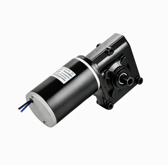
Performance Highlights: Output Speed and Torque: The motor offers a versatile range of speed and torque options, allowing for customization to suit specific application requirements. The gearbox provides precise control over speed and torque output. Efficiency: With its brushed DC technology and precision gearbox, this motor delivers high efficiency, minimizing energy consumption and heat generation. Reliability: The 7712Z motor is designed for continuous operation with minimal wear and tear, ensuring a reliable performance over an extended lifespan.
0 notes
Text
Open source 24-channel USB high-voltage driver
When it comes to automation and control systems, there's often a need for multiple digitally controlled output terminals with high-voltage handling capabilities. Many existing modules are bulky, expensive, or require numerous additional components to function. To address this gap, I've developed a fully open-source, USB-controlled 24-channel high-voltage driver. This device provides precise, flexible control in a compact and user-friendly package. The project is open hardware, released under the CERN-OHL-W license, ensuring transparency from hardware schematics to firmware code. The driver module communicates via USB using a simple virtual COM port, eliminating the need for special drivers and complex setups.

At the core of the system are three TPIC6B595 shift registers, each supplying eight open-drain outputs that can handle up to 50V and sink currents of up to 150mA per channel. These registers are daisy-chained to achieve a total of 24 outputs. The outputs are designed for low-side switching and include integrated clamping diodes, making them suitable for driving inductive loads such as relays and solenoids. Data is clocked into the registers through serial input from a microcontroller, allowing for fast and reliable state updates across all channels with just a few lines of code.
The logic and communication for this module are managed by the STC15W204S microcontroller, a cost-effective yet powerful 8051-based MCU with enhanced UART performance and an integrated oscillator. This chip is paired with a CH340N USB-to-UART bridge, which presents the device as a standard virtual COM port to the host PC. Upon connection, the microcontroller listens for a set of AT-style commands sent over the serial connection. These commands are straightforward and user-friendly, for example, "ON=65280" activates the middle 8 outputs, "CLR" turns off all channels, and "VER" retrieves the firmware version. Additionally, there is a command to save the current output state to the built-in EEPROM, enabling the system to restore its output to a known state after power cycles. This interface design is perfect for scripting, automation, or integration with software tools such as Python, LabVIEW, or custom control GUIs.
The PCB is designed using KiCad and features a 2-layer layout measuring 75.25mm × 33.75mm. It includes 2.54mm pitch headers for output connections and is equipped with a USB Type-C connector. Power can be supplied through either USB or an external regulated 5V source, which can be selected via onboard jumper settings. The layout ensures clean signal routing and minimizes crosstalk or interference, even when switching high-voltage loads. Careful decoupling and protection components provide robustness for real-world applications.

The PCB for this module was fabricated by PCBWay, who generously sponsored this project. PCBWay offers high-quality PCB manufacturing and assembling services. Also, they offer CNC and 3D printing services. The PCB of this module is available to order from PCBWay. Check out the PCBWay website for its manufacturing capabilities and pricing.
The firmware for the STC15W204S is written in C using SDCC. It is easy to expand the command set, introduce new communication modes, or add timed control logic as needed. The current implementation allows full 24-bit output control using a base 10 numerical mask, making it both scriptable and human-readable. Thanks to the preloaded bootloader of the STC15W204S, firmware updates can be performed through the same serial interface. Details about this process are covered in the project documentation. Like the hardware, the firmware is released under the MIT License and is available in the project repository.
The system has been tested with a variety of 12V and 24V inductive and resistive loads, including relay banks, solenoids, and LED arrays. Since the outputs are open-drain, external voltages up to 50V can be safely switched on each channel making it ideal for a range of industrial, laboratory, or artistic applications. Output timing is reliable, with clean edge transitions observed during scope testing, and no signal integrity issues even during full 24-channel toggling. It is recommended to use individual heatsinks for the driver ICs when driving high-current inductive loads with this module. While the printed circuit board has heat transfer traces, the addition of individual heatsinks can increase the durability of the module.

Potential use cases for this module include automated test benches, home automation systems, signal routing for instrumentation, nixie tube multiplexing, and other high-voltage control tasks. The command-based protocol makes it easy to script operations or integrate this module into a larger system.
For those who wish to explore the schematics, command protocol, design rationale, and usage examples in greater depth, I have published comprehensive documentation and resources in the project wiki. This includes detailed assembly instructions, firmware flashing guidance, and tips on customizing the firmware for enhanced functionality.
All source files - including schematics, PCB layout, firmware code, and the bill of materials - are freely available at https://github.com/dilshan/24ch-usb-high-voltage-driver.
0 notes
Text
What are the typical steps in firmware development?
Firmware development is a structured process that ensures the efficient and reliable operation of hardware devices. It typically begins with requirements gathering, where developers collaborate with stakeholders to define the device's functionality, performance, and constraints. Understanding these requirements early is crucial to avoid costly redesigns later.
Next is the architecture design phase. Here, the system is broken into modules, and decisions are made regarding hardware interfaces, memory usage, and real-time constraints. The architecture guides the development and ensures scalability and maintainability.
Following architecture, developers move to low-level hardware interfacing. This involves writing drivers that control hardware peripherals like timers, GPIOs, UARTs, and sensors. Close attention to datasheets and hardware manuals is essential in this step.
The application development phase builds the core functionality on top of the hardware abstraction. Developers implement features like control algorithms, communication protocols, or user interfaces depending on the product requirements.
Testing and debugging play a continuous role throughout firmware development. Unit tests, integration tests, and hardware-in-the-loop (HIL) testing ensure the system behaves correctly. Debugging often requires specialized tools like JTAG debuggers and oscilloscopes to analyze system behavior.
Once the firmware is stable, developers move to the optimization phase. They fine-tune code for performance, power consumption, and memory usage, which are critical for embedded systems.
Finally, deployment and maintenance occur. Firmware is flashed onto devices, and field updates may be delivered via mechanisms like OTA (Over-The-Air) updates. Ongoing support ensures firmware remains secure and functional over the device’s lifecycle.
Mastering these steps can be challenging but rewarding. Many professionals take an embedded systems course with placement to gain practical skills and successfully enter this field.
0 notes
Text
Understanding the 4 Core Components of an Embedded Linux System
Before diving into how to build a complete embedded Linux system, it’s important to know what major parts make up the system itself. A good way to understand this is by looking at the boot process — what happens when you power on a device like an embedded controller, industrial gateway, or smart gadget.
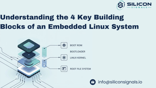
Each component plays a specific role in bringing the system to life, step by step. Here's a simple breakdown of the four essential parts of an embedded Linux system:
1. 🧠 Boot ROM – The Starting Point Inside the SoC
The Boot ROM is the very first code that runs when you power on your embedded device. It’s stored in read-only memory directly inside the System-on-Chip (SoC) and is similar to the BIOS on a standard computer. Although it's locked and can't be changed, it can react to external configurations (like boot pins) to decide where to load the next stage from – such as an SD card, eMMC, NAND flash, or even over UART/serial.
Some Boot ROMs also support secure boot by only allowing signed software to load next, adding a strong layer of security to the embedded system.
2. 🚀 Bootloader – Initializing the Hardware and Loading the Kernel
After the Boot ROM finishes its job, it passes control to the Bootloader. In many cases, the bootloader itself runs in two steps:
First stage: Prepares the system by initializing the RAM (since it's not ready right after power-up).
Second stage: Loads the Linux kernel from a chosen storage device or over a network (useful during development via TFTP).
Modern bootloaders also include features to:
Flash firmware or kernels onto memory devices like NAND or eMMC,
Test hardware components like I2C/SPI, RAM, and others,
Run Power-On Self-Tests (POST) to ensure system stability before launching the OS.
Popular bootloaders like U-Boot are often used in embedded Linux development for their flexibility and wide hardware support.
3. 🧩 Linux Kernel – The Core of the Operating System
The Linux Kernel is the brain of the system and is responsible for:
Talking to the hardware (drivers for peripherals),
Handling system tasks like scheduling and memory management,
Creating a stable environment for your applications to run.
It acts as the bridge between the hardware layer and the user space, making it possible to develop portable embedded applications that don’t rely on the specifics of the underlying board.
4. 📁 Root File System – The Application Playground
Once the kernel is up and running, its next task is to mount the root file system — the place where all applications, scripts, and shared libraries live.
Creating this from scratch is complex due to package dependencies and compatibility issues. That’s why tools like Buildroot, Yocto Project, or OpenEmbedded are used to automatically build and manage the root filesystem.
These tools help embedded developers customize and maintain a lightweight and reliable file system tailored to their device, ensuring consistency and performance.
Need Help Building Your Embedded Linux Solution?
At Silicon Signals, we specialize in custom embedded Linux development, including board bring-up, device driver integration, Android BSPs, secure boot implementation, and real-time optimizations.
Whether you're working on a new product or looking to optimize an existing one, our team can help you accelerate development and reduce risk.
📩 Contact us today to discuss how we can bring your embedded system to life. 🌐 Visit: www.siliconsignals.io ✉️ Email: [email protected]
#embeddedtechnology#embeddedsoftware#embeddedsystems#linux kernel#linuxdebugging#iot development services#iotsolutions
0 notes
Text
A Comprehensive Guide to Firmware Development

In the world of embedded systems and smart devices, firmware plays a critical role in enabling hardware to function effectively. Whether you're developing IoT devices, automotive systems, or industrial machinery, firmware development is the backbone that bridges hardware and software.
In this blog post, we’ll explore what firmware is, its importance, the development process, tools used, and best practices to ensure efficient and secure firmware solutions.
What is Firmware?
Firmware is a specialized type of software that provides low-level control for a device's specific hardware. Unlike regular software applications, firmware is tightly coupled with the hardware and is often stored in non-volatile memory such as ROM, EEPROM, or flash memory.
Examples of devices with firmware include:
Smartphones
Routers
Smart TVs
Medical devices
Automotive control units (ECUs)
Why is Firmware Important?
Firmware is essential because it:
Controls hardware operations: Without firmware, the hardware components of a device would be non-functional.
Ensures device functionality: It manages startup routines, I/O operations, sensor integration, and communication protocols.
Supports software-hardware integration: Firmware acts as a middle layer, allowing high-level software applications to interact with low-level hardware components.
Enables updates: Firmware can often be updated to fix bugs, enhance performance, or add features.
The Firmware Development Process
1. Requirements Gathering
Understanding the hardware specifications and the device’s purpose is crucial. Developers need to gather requirements from both hardware engineers and end users.
2. Architecture Design
This involves deciding on the architecture and communication protocols (e.g., I2C, SPI, UART), memory usage, and timing constraints.
3. Choosing a Development Platform
Most firmware is written in C or C++ due to their efficiency and hardware-level access. You’ll also need:
Microcontroller/microprocessor datasheets
Board Support Packages (BSPs)
RTOS (Real-Time Operating System), if required
4. Coding and Integration
Firmware code is written to interface directly with hardware. This includes writing drivers for peripherals (LEDs, sensors, motors) and managing power consumption, timing, and interrupts.
5. Testing and Debugging
Testing includes:
Unit testing
Hardware-in-the-loop (HIL) testing
Simulation and emulation tools
Debugging tools such as JTAG and SWD are used to step through code and analyze performance.
6. Deployment
Once tested, firmware is compiled and flashed onto the device using programmers or over-the-air (OTA) update mechanisms.
Tools Used in Firmware Development
Integrated Development Environments (IDEs): Keil µVision, MPLAB X, STM32CubeIDE
Compilers and Toolchains: GCC, IAR Embedded Workbench
Debuggers/Programmers: JTAG, ST-LINK, AVR ISP
Version Control Systems: Git
Simulators/Emulators: QEMU, Proteus
Best Practices for Firmware Development
Write modular and reusable code
Follow coding standards (e.g., MISRA C for safety-critical systems)
Optimize for memory and power consumption
Document thoroughly for maintainability
Implement fail-safes and watchdog timers
Secure your firmware (e.g., with encryption and secure boot loaders)
Plan for firmware updates with mechanisms like OTA updates
0 notes
Text
On Major Milestones
I left off previously with init immediately crashing when trying to run NetBSD on Wrap030, my 68030 homebrew computer. I was completely lost and didn't know where to start looking. The error code it gave, 11, didn't tell me much.
Until now, most error codes I've gotten have been defined in kernel errno.h, which has 11 defined as:
EDEADLK 11 /* Resource deadlock avoided */
That … also isn't helpful. I'm still not entirely sure what that means, but since this is process 1 we're dealing with, I didn't think it was relevant.
Finally, I was able to find someone who had encountered the same error six years ago. Helpful soul [Martin] explained the exact cause of the error, how to fix it, and why the kernel errno didn't line up:

I'm running a NetBSD live disk on a laptop as a test host, so I mounted my disk on it and spent some time with mknod adding the essential device nodes, referencing the "majors" file for my arch. Sure enough, on next boot it skipped right past the point it had been panicking. It worked for a bit then finally printed on the console:
Enter pathname o
Enter pathname of what? The machine appeared frozen. Nothing further printed, and it responded to no input.
I was afraid this would happen. That string is 16 characters. The 16C55x UART chips I'm using have a 16-byte buffer. The system is hung up waiting for the UART to interrupt to indicate it has finished transmitting everything in its buffer.
There's just one problem — I don't have any serial interrupts wired.
I have a confession to make. Until a few weeks ago when I got my timer working, I hadn't really worked with hardware interrupts before. So between a limited understanding of how to use them effectively and limited board space, I had omitted the interrupt signals from my 8-port serial card. This was now a Problem, and I was going to have to find a solution.
I had a few options:
Force the com driver to 8250 mode so it doesn't try to use the buffers
Use my timer interrupt to check status bits on the UARTs and fake the interrupts
Deadbug an interrupt handler onto my serial card
Respin the serial card
Option 4 would've been expensive and risked passing my deadline. I wasn't sure option 1 would even help. And option 3 would have been difficult and error-prone. I decided option 2 would be the way to go so I set about researching how to accomplish it
I spent a few hours digging through the com driver. In the process I found softintr(9), a native NetBSD software interrupt process that looked like just the thing I needed. Digging in a little deeper, I realized that the com driver was already using softintr. And then I realized all it needed to do polled mode serial ports instead of interrupt-driven was to set a single variable, sc_poll_ticks, before initializing the driver. It's such a simple thing, but it's not really documented anywhere I could find, so the only way to know it was even an option was to spend hours studying the code.
With that in place, I recompiled my kernel and tried again.

It was asking for a shell. This is promising. I accepted the default shell, /bin/sh, and waited a moment. It printed a single #.
I had a shell prompt.

I typed in the first thing that came to mind, echo "hellorld" (thanks, [Usagi]). It responded:
hellorld
and printed another # prompt.
I had a working shell.

This is a major milestone. I have a modern operating system kernel loaded and running on my homebrew computer, and I have a functional root shell. I can navigate disk directories and run commands and programs.
But only as root, and only on this one console. I have seven other serial ports I want terminals on, and I certainly don't want them all running as root.
What it's running here is single-user mode. It is just the kernel and a few core services, somewhat analogous to Safe Mode in Windows. It's a fall-back for setting up or repairing a system. It's not quite the full operating system just yet.
Getting the rest of the operating system up and running is going to be a significant task, on par with getting just the kernel running. Setting up a working Unix system from scratch is not easy. It requires a lot of detailed knowledge of the various programs and libraries and config files scattered across the disk. For a sense of scale, the AT&T Unix System V manual was over 1100 pages, plus an 800 page programmer's guide and a handful of other manuals … and that was 40 years ago. That's a lot of specialized knowledge that I don't really have.
But still, this is something I've wanted to do for years and after countless hours of work, I finally have a glimpse of what it can look like. I have a lot to learn and a lot of work to do yet, but I'm certain I can figure it out.
I'm still hoping I can get this running multi-user on all those terminals in time for VCF Southwest in June. The show is just a few weeks away and I have a lot of work to do.
#mc68030#motorola 68k#motorola 68030#debugging#wrap030#retrotech#troubleshooting#netbsd#at&t unix#unix#unixporn#operating systems#os development#retro computing#retrocomputing#homebrew computer#homebrew computing#usagi electric#vcfsw#vcf southwest
19 notes
·
View notes
Text

The SC16IS74x is an I2C to UART converter
If you know us, you know we luuuuuv I2C as a near-universal interface for sensors, GPIO expanders, OLEDs, and other various devices under our Stemma QT family: https://www.adafruit.com/search?q=stemma+qt 🌱. But we still bump into some UART devices: https://www.adafruit.com/search?q=uart here and there—GNSS/GPS units, MP3 playback chips, fingerprint sensors, LIDARs, and more.
These can be annoying if you only have one UART port-or none at all! So we put together this SC16IS74x breakout. It can use either the SC16IS740: https://www.digikey.com/en/products/detail/nxp-usa-inc/SC16IS740IPW-128/1301043 or SC16IS741: https://www.digikey.com/en/products/detail/nxp-usa-inc/SC16IS741AIPWJ/4486521 chips-both essentially the same for our purpose: providing a bidirectional UART with flow control. Address jumpers on the back allow you to select up to four devices on one I2C bus—and there's even native Linux kernel drivers: https://www.kernel.org/doc/Documentation/devicetree/bindings/serial/nxp%2Csc16is7xx.txt 🧠.
7 notes
·
View notes
Text
Raspberry Pi PiCAN FD HAT with LIN Bus Interface
This PiCAN FD board includes a LIN Bus interface, and the Microchip MCP2518FD IC offers classic CAN and CAN FD capabilities, while a dsPIC33 microcontroller facilitates the LIN Bus connection. Communication with the Pi occurs via UART on ttyS0 using ASCII text commands. A sample LIN-bus GUI application, developed in Python3 with tkinter, is available. The firmware can be updated through the Microchip UnifiedHost Java app, which requires the Raspberry Pi to operate in GUI mode. Installation of the SocketCAN driver is straightforward. Programming support is available in C or Python.
0 notes
Text
UHF Reader Based on Pico W & ESP32 with 50 Tags/Second Reading within 1.5 Meter Range

A UHF Reader (Ultra High Frequency Reader) is a device that is used to read and write data from UHF RFID tags within the 860MHz-960MHz frequency range. It is a multi tags 50 tags/second reading/writing device within 1-1.5 meter range designed with cutting edge UHF technology. It is a compact, portable and easy to use device.
The UHF reader has 2 variants: one is UHF Reader by Pico W and another is UHF Reader by ESP32. The Pico W variant comes with RP2040 microcontroller with Wi-Fi and BLE support. It is compatible with MicroPython, CircuitPython and Arduino for programming. ESP32 variant comes with ESP32 S3 series microcontroller and has 2.4GHz & Bluetooth 5 (LE) support. It is compatible with Arduino and Espressif IDE for programming.
Key Features and Specifications:
UHF Reader Pico Variant:

Powered by Raspberry Pi Pico W
RP2040 microcontroller dual-core Arm Cortex M0+ microprocessor with 264kB RAM
Supports Wi-Fi and BLE
1.14” TFT display for better visualization
Multi-tone buzzer for audio alerts
Micro USB Support for programming & Type C support for power
3 programmable buttons and Reset button
SD card slot for data storage/transfer
LED Status for power and battery charging
Multipurpose GPIOs breakout for interfacing external peripherals
SWD pins breakout for serial debugging
Supports MicroPython, CircuitPython, and Arduino for programming
UHF Reader ESP32 Variant:

Powered by ESP32 S3 WROOM-1
Dual-core 32 bit LX7 microprocessor with Up to 8 MB PSRAM and up to 16 MB flash memory
Supports 2.4GHz (802.11b/g/n) Wi-Fi and Bluetooth 5 (LE)
1.14” TFT display with ST7789 display driver
Comes with a Read and Write UHF module.
Frequency range of 865.1MHz-867.9MHz (for EU/UK) and 902.25MHz-927.75MHz (for US)
Can Identify 50 tags/second up to the 1.5-meter range.
TTL UART communication interface and communication baud rates 115200bps-38400bps
output power 18-26dBm and output power accuracy +/- 1dB
operation current 180mA at 3.5V (26 dBm Output), 110mA at 3.5V (18 dBm Output)
Multi-tone buzzer for audio alerts
2 user programmable buttons, Boot and Reset buttons
For power and programming support, the Type C Interface
SD Card slot for data transfer/storage
LED status for power and charging
Multipurpose GPIOs breakout for interfacing external peripherals
Supports Arduino and Espressif IDE for programming
By using ESP32 and RP2040, you can build a UHF RFID reader for scan tags and data tracking. This UHF Reader with ESP32 and Pico by SB Components is suitable for applications like warehouses, retail stores, and many other applications where you want to track your inventory data accurately.
#technology#innovation#tech#iot#rfid#uhf#uhf reader#arduino#espressif#iot applications#raspberry pi#rp2040#esp32#projects#programming#ultra high frequency reader#rfid tags#data tracking#electronics
1 note
·
View note